
Correcting For Bi-Axial Force Sensor Crosstalk
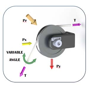
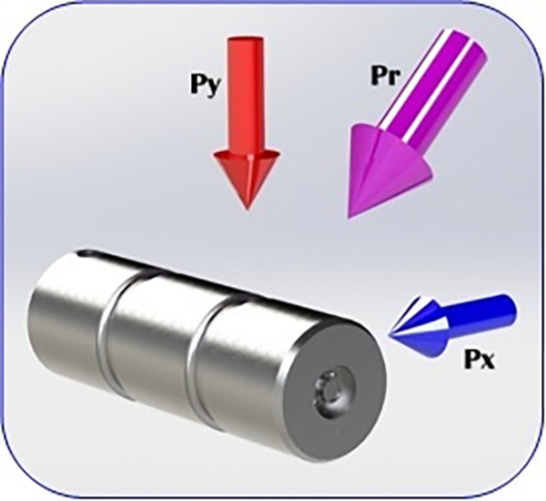
Bi-Axial force sensor pins are designed for applications where it is necessary to measure an applied force (Pr) at a varying angle, relative to the X and Y axes. Applications typically include either a Clevis Pin or a Sheave Pin installation as shown below. When a force is applied at an arbitrary angle, a strain meter measures the force components in both X and Y directions. Ideally, the value of the strain meter readings for both X and Y axes will always be geometrically proportionate for any arbitrary angle of applied force. However, typical sensor system measurements may vary due to a condition called Crosstalk.
Crosstalk is unavoidable due to the physical constraints of the sensor body and gage installation. It is typical on all Bi-axial force sensors regardless of manufacturer. The amount of Crosstalk in each individual sensor will vary and is unique depending on several factors that are difficult to impossible to control. To further complicate matters, the conditions of the target installation versus the manufacturing facility may possess larger than acceptable differences, regardless of best efforts to minimize the differences. Bi-Axial sensor manufacturers will sometimes expend often costly efforts to minimize the effects of Crosstalk. Unfortunately, these efforts simply are not able to anticipate the unknown differences that will be encountered in the target application.
Pr=√( &〖Px〗^2+〖Py〗^2 ) Ideal Bi-Axial Pin (no Crosstalk)
Pr≠√( &〖Px〗^2+〖Py〗^2 ) Typical Bi-Axial Pin (with Crosstalk)
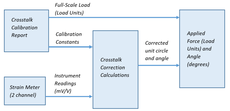
To reduce the effects of Crosstalk, mathematical correction is a better and more complete method. The correction is calculated using a set of fixed equations, calibration constants, and strain meter readings.
Crosstalk calibration is performed at the manufacturing facility under ideal conditions. The calibration generates the factory calibration constants. After the system is installed, an in-place system calibration is also recommended. This will generate a new set of calibration constants. The new in-place calibration constants will then be used instead of the factory calibration constants because they are refined to the actual conditions of the installation. Fortunately, the in-place calibration is not constrained to the same angle and force measurement requirements that were used during factory calibration.
When applied, the mathematical correction provides the best possible measurement in the form of a corrected unit circle (range between 0 and 1 for loads between zero-scale and full-scale, respectively). Additionally, the correction provides a more accurate angle of applied force.
Corrected strain meter measurements are geometrically proportionate to the sensor. To calculate the resultant force components in load units, simply multiply the magnitude of the corrected unit circle to the Full-Scale Load. If required, simple geometric equations may be used to convert between Cylindrical and Cartesian coordinates.
The accuracy of readings on older/existing installations will benefit from an updated in-place calibration using this method. Also, periodic in-place recalibrations are possible.
Automation of Crosstalk Correction is recommended, due to the low cost and ready availability of technology. For more information, support for in-place calibration, or for assistance in Crosstalk Correction automation, contact Strainsert.