
Instrumented Load Pins for Sheave Applications
Instrumented Load Pins for Sheave Applications
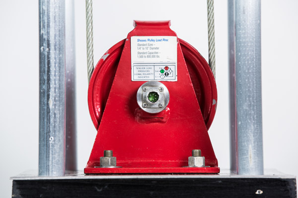
Strainsert Instrumented Load Pins for Sheave Applications are designed for sheave and pulley systems. The user has the option of either designing a sheave around our standard CPA Load Pin series or having a custom load pin manufactured for an existing sheave design with a tailored measurement capacity and geometry, allowing for simple installation and optimized measurement capacity. The Instrumented Sheave Load Pins are often used to measure line tension by monitoring reaction load on the pin. Using the equations provided below, the line tension can be determined.
Strainsert factory calibrations are intended to simulate installed conditions, however, it is recommended that an in-place calibration be performed to account for any installation, tolerance, and/or alignment influences affecting sensor measurement.
Click Here for our Load Pin Quick Start Guide for help with setup and installation of our Load Pin products.
Constant Wrap Angle
*Axis of Maximum Sensitivity: Align Keeper Flat of Load Sensing Pin perpendicular to Axis of Maximum Sensitivity which is at one half the wrap angle. For this example, wrap angle = 105 degrees and Ø/2 = 105 /2 = 52.5 degrees. See specification drawing below.
Ø= Wrap Angle
T = Line Tension
P = Resultant Force on Sheave Pin
Line Tension (T): To measure the tension in a line by measuring the reaction force on the sheave use the specification drawing and formulas:
P = 2T cos(Ø/2) or T = P ÷ 2cos(Ø/2)
Example:For a Wrap Angle of Ø = 105 and measured sheave load of 10,000-lbs. The Line Tension (T) can be determined by the formula:
Variable Wrap Angle
The cross section of the bi-axial load pin illustrates gage alignment. The gages marked Y will sense load component Py, while the gages marked X will sense loads in the Px direction. Given the outputs from the two bridges as Ex and Ey, and constants (Kx,Ky), derived from calibration data*, the resultant force P is determined by:
Px = Kx Ex
Py = Ky Ey
and the resultant force P = Square root of [Px]² + [Py]²
The Line Tension (T) and Wrap Angle (Ø) can be determined by:
T = Px² + Py² ÷ 2Px and Ø = 2 inverse cosine( P ÷ 2T)
*Where P, Px and Py are adjusted for cross-talk effects. For further discussion of bi-axial load pins see bi-axial pins under the Clevis Pin Optional Features
Variable Wrap Angle Specifications
Pin Design: For quotations on custom sheave pin designs, Contact Us at 610-825-3310 or complete our form. Include additional drawings, comments, or special requirements as applicable.
Full Specs
| Bridge Composition | Bridge Excitation | Bridge Resistance | Bridge Sensitivity | Material | |
|---|---|---|---|---|---|
| Variable Wrap Angle | Full | 10 (typical), 12 maximum Vdc | 350 (nominal) Ohm | 0.5 and higher mV/V | 17-4 Stainless Steel (typical) |
| Constant Wrap Angle | Full | 10 (typical), 12 maximum Vdc | 350 (nominal) Ohm | 0.5 and higher mV/V | 17-4 Stainless Steel (typical) |