
Standard Load Cell Installation Instructions
Specifications
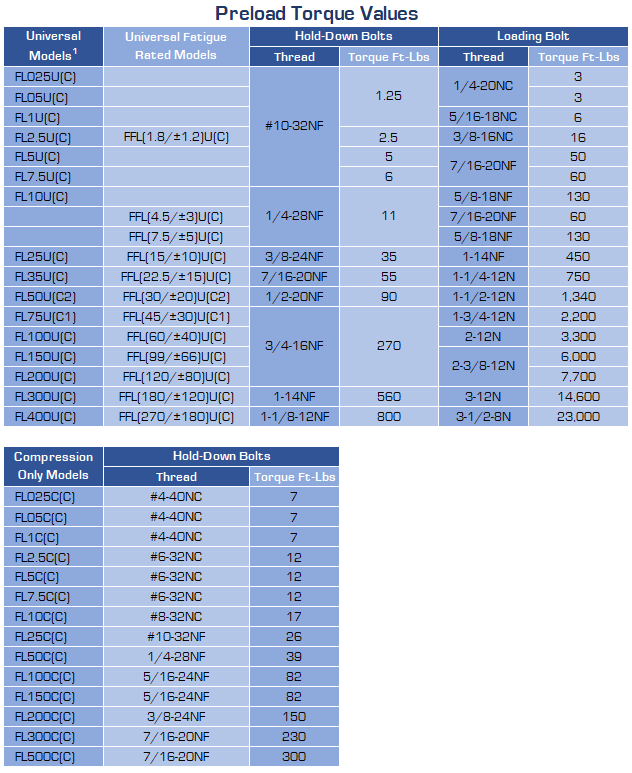
C. Loading Bolt Torque:
Loading Bolt preload requirements may be modified according to the following conditions:
- Uni-Directional, Low Cycle, Low Frequency*, or Static Loading Conditions do not require any preloading torque.
- In all modes of loading, other than (1.) above, loading bolt torque values apply. (See Torque Values table).
- For Load Cells with through loading holes (without threads), above detailed preloading conditions must be simulated.
*Approximately 1-Hz, depending on masses involved and magnitude of inertia forces generated.
 U.S. Patent No. 3,365,689
Notes:
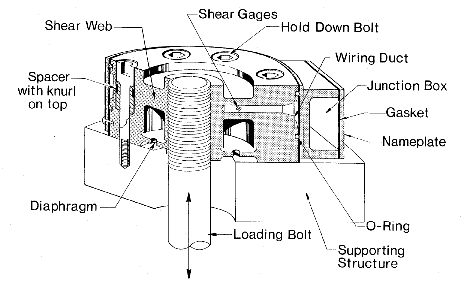
- Universal & Fatigue Rated Flat Load Cells require high strength socket head cap screws, with corresponding torque valves, and spacers as illustrated.
- Torque values given are for lubricated threads.
- The Loading Bolt must engage all the threads in the Load Cell threaded hole.
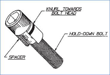
- Spacers should be used with the knurl towards the bolt head.
Spacers for Flat Load Cells in conjunction with Hold-Down Bolts
![]()
The purpose of spacers is to prevent loosening of Hold-Down Bolts.
Universal & Fatigue Rated Flat Load Cell Hold-Down Bolts must always be tightened to specified torque values, to maintain original calibration performance, regardless of the magnitude of the load.
One of the reasons for tension loss in tightened bolts is because microscopic thread surfaces in bolts and mating threads are not smooth, but consist of peaks and valleys, as illustrated. Thus, threads are engaged at correspondingly higher than average stress levels, causing continuous crumbling of such high spots. This reduces the elongation of the bolt imparted by tightening.
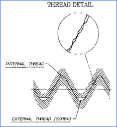
The longer the bolt, the larger the tightening elongation. In a short stubby bolt, loss of tightening elongation due to thread crumbling can be very serious. To reduce this effect to a manageable condition, spacers are used. Spacers add to the length of the bolt, as well as provide some additional deflection themselves, and help maintain the desired bolt preload.
Strainsert – for superior internally gaged force transducers.
Strainsert stands for:
- Product Quality
- Knowledgeable Technical Staff
- Standard and Custom Designs
- Customer Service
- Comprehensive Testing
Contact Strainsert
For information on load pins, force sensing bolts, load cells, tension links or our high quality custom products, Contact Us for further assistance.