Load Bolts and Studs General Product Information
Strainsert load bolts and studs utilize an exclusive internal gaging method (U.S. Patent #2,873,341) to indicate bolt tension due to preload with strain gage accuracy.
Load bolts and studs provide a means for accurate, independent inspection of an assembled bolt for preload, thereby enhancing the structural integrity and reliability of both the bolt and the assembly.
Features
Some Features Include:
- Measurement of preload induced in load bolts and studs
- Uniform fastener tightening in a bolt pattern
- Use of load bolts and studs as load link transducers
- Accurate tightening within 1% of load typically
- Overload detection in bolted machinery
- Quarter; and full bridge configurations
Strainsert Fasteners Offer
- Bolts with Full Load Carrying Capacity – Bolts with Strainsert internal gage installations have the full load carrying capacity of the original ungaged bolt. Cross-sectional area of the threaded portion of a full shank bolt is always smaller than the cross sectional area of the shank. The difference in areas permits a hole to be drilled in the shank for the gage installation without weakening the bolt. (1/4” diameter and smaller bolts may have reduced load carrying capacities).
- Guaranteed Accuracy – Giving precise calibration and accuracy guarantees for Strainsert Bolts and Studs is not a simple matter. Most gage installations are in fasteners supplied by the customers or purchased from the fastener manufacturers. Therefore, Strainsert does not control the supplied fasteners material, design or quality.
- For this reason, Strainsert Bolts and Studs to have a combined error due to repetition, nonlinearity and hysteresis of, typically, less than 1% of maximum load. Actually, the combined error is usually less than 1/2%.
- Loading of Gage Installations – Prior to shipment, all gage installations are calibrated as part of the quality control procedure. Unless otherwise specified, bolts and studs are normally loaded to approximately 70% of yield.
Internal Gage Installations
Gages installed in Strainsert Bolts and Studs are foil type, electric resistance strain gages. They are bonded and sealed in a small hole along the longitudinal neutral axis of the bolt. After installation the gages are practically immune to physical and environmental damage and the gages in a full-bridge internal installation are located very close to each other in a relative uniform temperature environment.
Internal gage installations by Strainsert are as good as the very best external gage installations. The patented installation technique has been proven over forty five years of service.
Gage Configuration Compensates For Bending And Torque
Quarter-bridge installations consist of two gages in series mounted 180 degrees apart on the circumference of the hole with the grid in an axial direction. This arrangement provides the best indication of bolt load and also helps minimize bending and torque influences. To eliminate lead-wire temperature effects, a three-wire lead system is used. Trim resistors or other compensations are not furnished with quarter-bridge gage installations.
Full-bridge internal gage installations are made in the same size hole as for quarter-bridge. They are wired as shown with axial active gages and circumferential complementary gages. Trims and compensations are offered only if there is room for the necessary components.
Load Sensing Bolts And Studs In Bolted Structures
When structures are joined together by tightening a bolt or a stud, a tension force is induced in the shank of the fastener. This tension force causes a compressive or clamping force on the joined members. In the absence of other external forces, this clamping force is exactly equal to the tension in the bolt or stud. Thus, a load sensing fastener will provide very accurate measure of such clamping force.
In service, bolt preload may be relieved due to one or more causes. This could result in malfunction or failure. Ability to measure bolt load by means of load sensing bolts can avoid such difficulties. It is important, however, to make measurements on the bolted assembly when no external or service load are present in order to have direct before and after comparison.
Load sensing bolts and studs can thus be very useful in detemining effects of operational service loads, although it should be clear that the bolts do not directly measure service loads. One exception to this occurs when the service load is larger than the clamping preload, resulting in joint separation. Under this condition, the service load is equal to the bolt load, which is measured accurately by the load sensing bolt.
When the operational service load only partly relieves the compressive force at the joint, but is too small to cause separation, or when service load is in the direction increasing joint compression, then the bolt load is no longer equal to either the compressive clamping force or the service load. It is equal to their difference. There may be a small change in the bolt load as the service load is applied, but this will be far smaller than the service load, which will mainly increase or decrease the compressive clamping force on the joined members. The bolt load change due to service load will depend mainly upon the relative stiffness between the bolt and the bolted member, as well as other variables. Determination of service or external loads in a bolted joint by means of preloaded load sensing bolts is not recommended.
Lead Wire Terminations
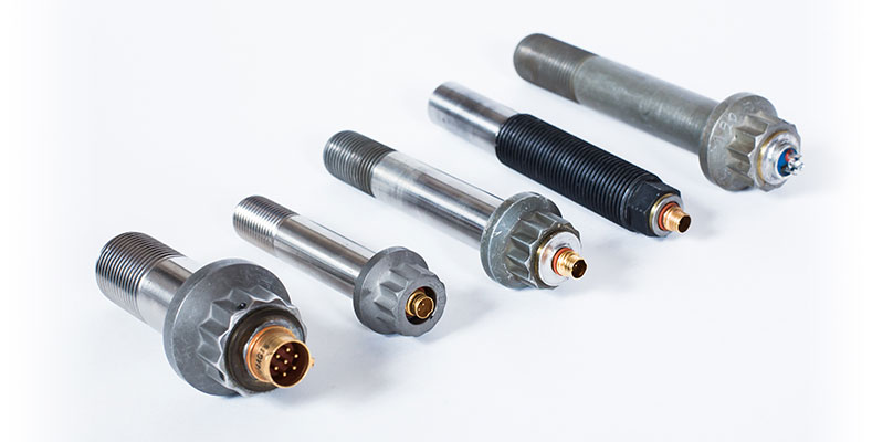
Three basic lead wire terminations are available for bolts and studs:
Type C – screw type miniture connector, requires mating cable assembly.
Type H – a multi-pin header for solder lead wire connections
Type W – Permanent factory installed cable
Quarter- and full-bridge internal gage installations can be made in bolt sizes down to 1/4″ diameter.
All the above three types of lead wire terminations are available on bolts of 1/4-inch diameter and larger.
1/4″ diameter screws are available as Type H or Type W only. Type C available with raised adapter.
Lead wire configurations for smaller size studs depend on size. Contact us for information on the ST Series Studs.
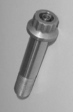
Bolt Grip Length Requirements
For proper performance the gage installation in a bolt should be below the head in the unthreaded section of the shank. This is the point where strain is most representative of bolt load. Minimum grip lengths recommended for various bolt sizes are shown below.
| BOLT DIA (inches) | 1/4 | 5/16 | 3/8 | 7/16 | 1/2 | 9/16 | 5/8 |
| MIN GRIP LENGTH (inches) | 7/8 | 1 | 1 | 1 | 1-1/16 | 1-1/8 | 1-1/4 |
| BOLT DIA (inches) | 3/4 | 7/8 | 1 | 1-1/8 | 1-1/4 | 1-3/8 | 1-1/2 |
| MIN GRIP LENGTH (inches) | 1-3/8 | 1-1/2 | 1-5/8 | 1-3/4 | 2 | 2-1/4 | 2-1/2 |
*Bolts with shorter grip lengths are gaged on special order.
Specifications
Strainsert Bolts/Stud General Specification Table
- Load bolts and studs can be accurately tightened and the preload measured to a tolerance of better than 1% of the maximum load typically. This method can replace the most common method of measuring load with a torque wrench with load measurement accuracy many times worse than +/-20%.
- Bolted equipment can be inspected after assembly to measure preload on a tightened bolt.
- Internally gaged fasteners strategically placed in equipment can act as built-in sensors for overload detection.
- Assemblies can be monitored and inspected under simulated or actual service conditions to see if any external forces exceed the preload. Overloads due to vibration, shock, etc. can be easily measured at any time during the life of the assembly.
- Bolts may be permanently installed providing very accurate analysis of bolt loading over a continuous time period. In applications of this type, internally gaged bolts become a new basic research tool.
- Gaged bolts and studs can be used as tension load cells or modified for compression applications.
Options
Calibration Service Available
For applications which require the utmost in accuracy, detailed calibration data can be supplied on order for any Strainsert Bolt and Stud. Loading is done in five equal steps up to maximum load; unloading is done in similar steps in reverse. The entire calibration process is repeated three times. For each step-load, the strain reading or signal is recorded.
Calibration readings are analyzed and compared to either a best fitting or customer specified straight line calibrations. Linearity, repetition, and hysteresis are determined from the data. For calibrations up to 500,000 pounds, in-plant loading facilities are used. Bolts or studs which require higher loads are calibrated on other suitable devices. Please see the calibration section for further discussions of calibration options.
Strainsert - for superior internally gaged force transducers.
Strainsert stands for:
- Product Quality
- Knowledgeable Technical Staff
- Standard and Custom Designs
- Customer Service
- Comprehensive Testing
Contact Strainsert
For information on load pins, force sensing bolts, load cells, tension links or our high quality custom products, Contact Us for further assistance.