Bi-Axial Load Pins
Bi-Axial Load Pins
Bi-Axial Load Pins are designed for applications that measure a radially applied force (Pr) where the load direction is unknown and/or changing in direction. This is facilitated by the installation of 2 perpendicular strain gage bridges (Px and Py), instrumentation, and geometric calculations.
One common use for a Bi-Axial Load Pin is at the hub of a sheave (or pulley) system, which is used to measure line tension. A Bi-Axial Load Pin installation has one end of the line at a fixed angle as a reference while the other end will vary in angle.
Common applications include sheave applications with variable angles, rotating joints, hinge pins, aircraft components (ex. landing gear), loader buckets, hydraulic actuators and mooring lines.

Specification Detail
- Bridge Composition – Full
- Bridge Excitation – 10 (Typical), 12 Maximum – VDC Units
- Bridge Resistance – 350 Ohms (Nominal)
- Bridge Sensitivity – 0.5 or higher mV/V
- Temperature, Zero – ±0.01% (Nominal) – F.S/°F
- Temperature, F.S. – ±0.01% (Nominal) – Load/°F
- Zero Balance – ±3.0% (Nominal) – F.S.
- Non-Repeatability – ±0.25% (Nominal) – F.S.
- Non-Linearity – ±1% (Nominal) – F.S.
- Hysteresis – ±1% (Nominal) – F.S.
- Safe Overload – 150% (Typical) – F.S.
- Ultimate Strength – 300% (Typical) – F.S.
- Minimum Pin Diameter – 1 (Standard), 0.5 (with limitations) – Inch
- Pin Material – Stainless Steel 17-4; or higher strength stainless or alloy steels
- Crosstalk Error, After Correction – 5% (Maximum), <2% (Typical) – F.S.
Crosstalk Description
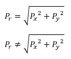 Crosstalk error is observed when a radial force (Pr) is applied at varying angles and the sensor output magnitude does not fit the expected circular pattern. Instead, there are higher-than-expected readings at angles between the primary X and Y axes. This error is primarily caused by internal strain gage transverse sensitivity, which is due to physical design and construction constraints. Ideally, the ratio of transverse-to-axial sensitivity is negligible, however, this is not always the case in practice. Crosstalk error is unique and variable to each individual sensor Therefore, crosstalk errors may be marginal and crosstalk corrections may not always be required.
Crosstalk Correction
Crosstalk error mitigation efforts during sensor build may be difficult or impossible to achieve physically, regardless of technique or manufacturer quality. Therefore, to minimize the effects of crosstalk error, a mathematical correction is the most complete and preferred method. Strainsert has developed a mathematical crosstalk correction process, which provides realistic data that can be used in force analysis and stress calculations.
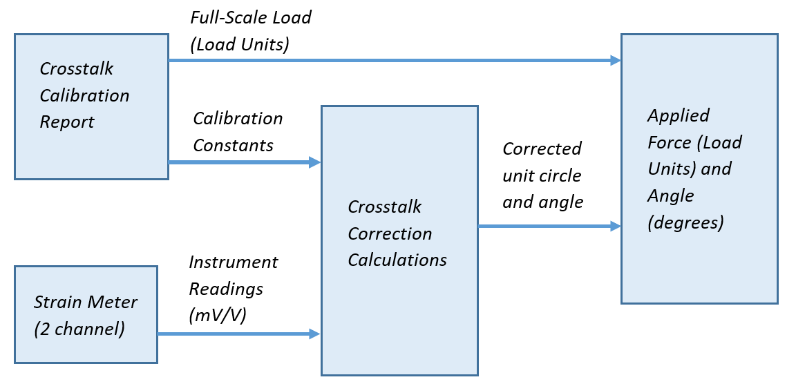
The inputs to the crosstalk correction function are the bi-axial strain readings and calibration constants. The calibration constants are determined during factory and/or in-place calibration.
The outputs of the crosstalk correction function are both Px and Py, which may be converted to Pr and angle (θ). This results in the most accurate measurement possible and is in the form of a corrected unit circle (range between 0 and 1 for loads between zero-scale and full-scale, respectively). This output may then be multiplied by the full-scale load value to determine the applied force in load units.
To determine the calibration constants, a factory crosstalk calibration is performed at Strainsert. For each crosstalk calibration, a Strainsert Crosstalk Correction Data report is provided. The crosstalk calibration consists of a series of angle measurements which can be either standard or customized to within a specified quadrant (0° – 90°, 90° – 180°, etc.). If the conditions of the target installation versus factory calibration are larger than expected, additional error may be introduced. Therefore, an in-place calibration is recommended after the clevis pin is installed. Using customer provided data, Strainsert will generate and provide an in-place Strainsert Crosstalk Correction Data report. The in-place calibration constants will then be used instead of the factory calibration constants.