Load Pin Installation Instructions
To maximize measurement accuracy and performance of the Strainsert Load Pins, please use the following load pin installation instructions, including; load pin orientation/loading, dimensional requirements, and material properties are provided. In addition, Strainsert factory calibrations are intended to simulate installed conditions, however, it is recommended that an in-place calibration be performed to account for any installation, tolerance, and/or alignment influences affecting sensor measurement.
Click Here for our Load Pin Quick Start Guide for help with setup and installation of our Load Pins.
1. Load Pin Orientation and Loading
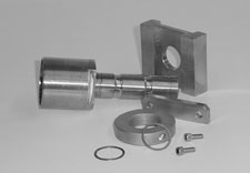
The purpose of the Anti-Rotation Devices is to provide and maintain proper angular alignment of the Load Pin/Bolt with the load P. Strain Gage circuit orientation in the Load Pin/Bolt is based on load angle.
With the Clevis structurally fixed in position, and the load P applied through and in the axial direction of the Eye, but at a varying angularity with the Clevis, a Key Pin type (A) Anti-Rotation and Retaining Device may be required. When forces involved, and Pin/Bolt size or circumstances allow, a different type Key (D) may be considered in such cases.
When the Eye is in a structurally fixed position, and the loads P/2 are applied through and in the axial direction of the Clevis, but at varying angularity with the Eye, then a Keeper Plate (B or C) type Anti-Rotation Device will be required.
In Pin/bolts with DP less than 2-inches, the Keeper Plate (C) will retain in one direction only, requiring a Retaining Ring or Nut. (However, no axial forces should be applied to the Clevis Pin during installation or use.)
Spacers are sometimes useful to take up excessive clearance between the Clevis and the Eye, to minimize the lateral motion of the Clevis Pin/bolt, and to fix the location of the internal Strain Gage Installations in the shear planes between the Clevis and the Eye. Please see our clevis pin specification drawing below for further details.

Specifications
2. Recommended Dimensional Requirements and Material Properties
The performance of instrumented Clevis Pins depends upon the quality and strength of the Clevis Pin metal and of the dimensional accuracy of the pin. The total performance of the pin also depends upon the quality and strength of the Clevis and Clevis Eye where the Clevis Pin is assembled.
The two important characteriestics of the Clevis and Clevis Eye are:
- Diametral clearance between pin and Clevis
- Compressive yield strength of the bearing surfaces that apply load to the Clevis Pin.
The length of the bearing surfaces compared to the pin diameter are also important but only when these dimensions are either too long or too short. Under normal proportions of the pins as illustrated in the Strainsert CPA information, the length is not a critical factor.
Recommended Clearances between Clevis Pin, Clevis and Clevis Eye
This depends upon practical considerations, and technical aspects. The clearance is a function of diameter, and the following values are recommended for typical applications:
PIN DIAMETER, INCH
0.375 in. to 1.000 inch
1.000 to 2.000 inch
Larger than 2.000 inch
PRECISION FIT MIN. CLEARANCE
0.0010 inch
0.002 inch
0.001 inch per inch dia
AVERAGE FIT CLEARANCE
0.002 inch
0.003 ins to 0.004 inch
0.0015-0.0020 inch per inch dia.
LOOSE FIT MAX. CLEARANCE
0.004 inch
0.006 ins to 0.010 inch
0.004 inch per inch dia.
Larger clearances are not a serious problem as far as accuracy is concerned. This, however, will increase the contact stress between clevis pin and clevis as illustrated in the specification drawing below.
Thus, if large clearances are used, the assembly will be accurate only at lower loads. At high loads, the yield stress in the clevis metal may cause measurement errors not due to the clevis pin.
Recommended Material Properties of Clevis and Clevis Eye (Please see specification drawing below)
The bearing stresses between the clevis pin, the clevis and clevis eye are larger than the average calculated stress obtained by dividing the load by bearing area.There are two factors that cause this increase, are as follows:
- Clearance between pin diameter and the bored holes
- Non-uniformity of the load along the supported length of the clevis pin.
I. Diametral Clearance of Pin
The effect of diametral clearance is graphically shown below in the end-view of the load pin. When the clearance is very small, the contact region approaches the entire pin diameter. As the clearance ratio increases, the contact area is reduced, and the total force is distributed over a smaller area. Thus, the bearing strength of the clevis can be lower when the clearances are smaller, assuming that the same force is to be measured by the clevis pin.
II. Non-Uniform Force Distribution along the Length of the Load Pin
This effect is illustrated in the side view of the pin. The approximate load distribution on a typical clevis pin along its length is shown by the shaded area. The load is a maximum at the inner edges of the clevis and at the outer edges of the clevis eye. The exact distribution varies from one installation to another. It is assumed that the two bored holes in the clevis are accurately in line, so that the pin is not “tilted” when installed. It is important to consider that the length dimensions A and B cannot be increased indefinitely to increase the strength of the bearing surfaces.
Drawing

Strainsert - for superior internally gaged force transducers.
Strainsert stands for:
- Product Quality
- Knowledgeable Technical Staff
- Standard and Custom Designs
- Customer Service
- Comprehensive Testing
Contact Strainsert
For information on load pins, force sensing bolts, load cells, tension links or our high quality custom products, Contact Us for further assistance.