
Load Cell Technical Information
Load Cell Technical Information
Load Cell Mechanical Properties
 Deflection, Spring Rate, and Natural Frequencies for Universal and Compression Load Cells are given in tabular form.
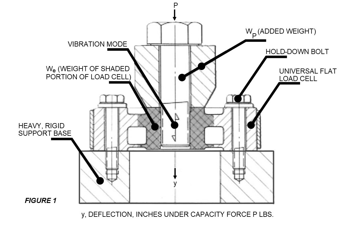
These mechanical properties of the load cells are based on the installation of Figure 1, in which the outer rim of the cell is clamped to a heavy, rigid base which deflects negligibly under load, and does not vibrate when excited by the load cell forces. (See figure to right)
The force P is applied axially at the center of the load cell.
Deflection y represents the axial deflection of the cell under capacity load P.
The Spring Rate K = P/y is the Stiffness of the load cell in the axial direction, and is the ratio between the force P and deflection y.
The effective weight We is that portion of the load cell weight which is gray shaded in Figure 1. It consists of the weight of the center hub and inboard parts of the reduced section and diaphragm which vibrate at or near full amplitude when the load cell is dynamically excited. The outer rim of the load cell and adjacent parts (not shaded) are assumed to be motionless, since they are held by the heavy base. The effective vibrating weight of the load cell is different than shown, when its outer rim is flexibly supported and participates in the vibration.
The tabulated values of axial natural frequency fc are those obtained when no weights Wb are attached to the hub of the load cell, which vibrates freely. By definition, this is the natural frequency of a single-degree-of-freedom system consisting of spring K and weight We. This is the highest possible axial natural frequency of a load cell installation, since any loading member will add mass to the center, hence, reduce the frequency.
Features
In order to give an example of natural frequency reduction as weight is added to the hub, values of natural frequency fp are listed for each load cell for the case when this additional weight Wp is equal to 0.001 P, as illustrated in Figure 1. Thus, the 50,000 pound capacity Universal Load Cell with 2-mv/v sensitivity, has a natural frequency of 11,400 cps without and added weights, but this reduced to a natural frequency fp of 2,000 cps when a weight Wp of 50 pounds is added.
To determine the axial natural frequency fx of any load cell system with any other added weight Wp (pounds) while rigidly supported as in Figure 1, the following equation may be used:
fx = 3.13[Square Root of (K/(We + Wp))]
When the external weight Wp is relatively large, its motion may have to be restricted to the axial vibration mode by means of suitable guides. If not, natural frequencies of lateral modes could possibly be lower than those tabulated.
All tabulated values are obtained by analysis, and expected accuracy is within 15 to 20 percent.
EXTRANEOUS LOADING CAPABILITIES OF UNIVERSAL LOAD CELLS
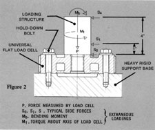 The Universal Load Cells are designed to with-stand extraneous loadings, in addition to the measured axial force P. Some typical extraneous loadings are tabulated, and are identified in Figure 2. These are lateral loads So (along the top of the cell), S1 (acting 1-inch above the top of the cell), and S4 (acting 4 inches above the top of the load cell). Also shown are bending moment Mb and torque Mt , applied to the center hub of the cell. It is assumed that any one of these would be applied individually, and not in combination with each other.
The tabulated values of extraneous loadings, applied individually will not cause permanent damage to the load cells. Allowable extraneous loadings are approximately half the values tabulated if applied in conjunction with other extraneous loads or measured load P.