Force Sensor Calibration
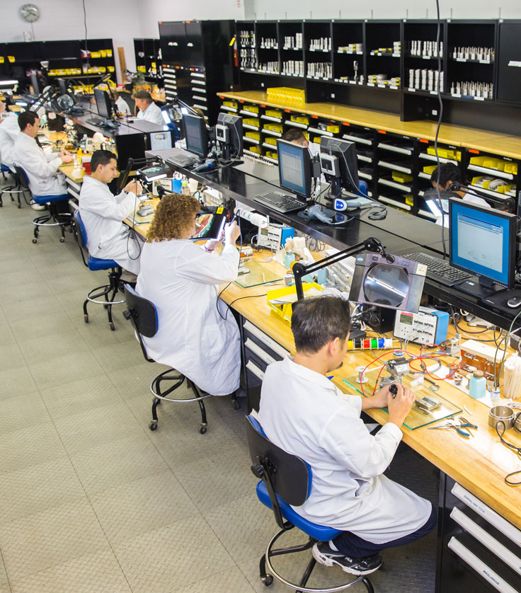
Strainsert’s calibration facilities enable Strainsert to certify all our manufactured products at our manufacturing site up to a 500,000 pound capacity. All Strainsert force measurements are traceable to the National Institute of Standards and Technology (NIST) and are performed by a highly-trained and experienced staff in a controlled environment.
Calibration entails completing a set of procedures comparing the accuracy of a measuring device, like a load cell or load pin, against the currently recognized standard or adjusting the load cell or load pin to bring it back into compliance with said standard.
Why Is Calibration Necessary?
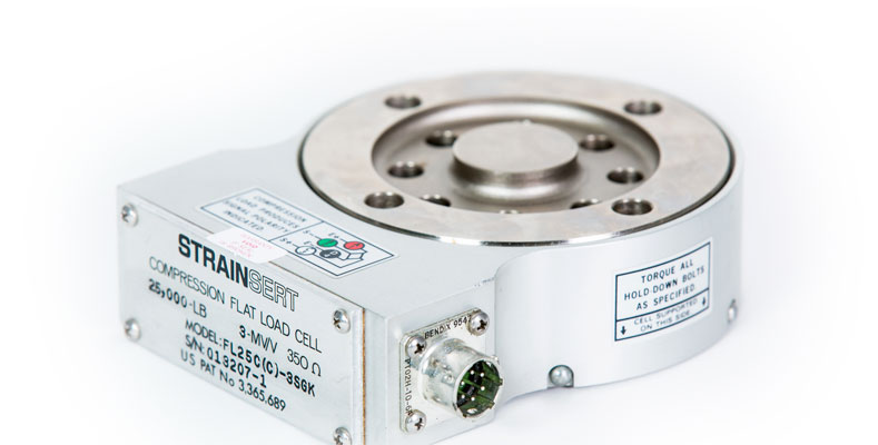
A load cell is an instrument utilized to measure force or weight in various applications. The load cell is a force sensor used to convert a force into an electrical signal. Strainsert load cells and load pins are strain gage transducers. This well established technology has been proven for over fifty years.
Load cells are frequently used as part of a weighing system because they offer non-intrusive, highly accurate load measurement data, with properly installed and calibrated load cells achieve accuracies of around 0.03 to 1% (depending on load cell type). These systems are critical to many industries including aerospace, marine, oil/gas exploration, military, aviation and automotive. Product liability and safety issues demand that force measurements are demonstrably accurate. Strainsert’s focus on traceability to NIST standards is also a requirement for compliance to ISO and AS certifications.
As all load cells are subject to deterioration due to use, mistreatment, drift or aging, calibration at regular intervals should to be carried out to establish how the load cell is currently performing, irrespective of whether the company has a Quality Management System in place. Load cells can also become less reliable due to electrical influence, mechanical effects, instrumentation faults and loose cables etc. Failure to inspect or clean load cells is another significant factor that can lead to operational issues, as particulate matter can build up around load cells even in clean environments. Unless calibrations are routinely carried out, load measurement readings can become less and less accurate, with the user potentially being unaware that they are using flawed data.
Strainsert calibration services include:
- Factory-site Calibrations to 500,000-lbs.
(Calibration capabilities to 4,000,000-lbs. are available in partnership with a local calibration facility) - NIST Traceability
- Detailed Calibration Reports
- Tension and/or Compression Calibrations
- Compliance with ANSI/NCSL Z540-1 and MIL-STD-45662A Specifications (Optional)
- Complete System Calibrations Available
- Special Overload / Proof Load and Additional Testing
Standard Strainsert Calibrations:
All of Strainsert’s standard calibration procedures result in a customer report that includes the product model and serial number, rated capacity, test load(s) applied, output sensitivity recorded at each test load, and a statement certifying traceability of the measurements. Customer calibration certificates are now available online if the calibration was performed by Strainsert within the last six months.
Stainsert offers several different calibration procedures and corresponding reports based on the customer’s requirements and product design criteria.
Available Standard Strainsert Calibration Procedures:
| Procedure | Bolts | Studs | Single Bridge Load Cells | Dual Bridge Load Cells | Tension Links | Single Axis Clevis Pins | Dual Bridge Clevis Pins | Clevis Pins Bi-Axial |
|---|---|---|---|---|---|---|---|---|
| PL | ||||||||
| CAL2-LO | ||||||||
| CAL2-LU | ||||||||
| CAL5-LO | * | * | * | |||||
| CAL5-LU | * | * | * | |||||
| CALIN-LO(**) | ||||||||
| CALIN-LU(**) | ||||||||
| CALSC-LO(**) | ||||||||
| CALSC-LU(**) | ||||||||
| CALXX-LOD | * | |||||||
| CALXX-LUD | ||||||||
| CALXX-LOBD | * | |||||||
| CALXX-LUBD | ||||||||
| ANSI/NCSL Z540-1 | ||||||||
| MIL-STD-45662A |
*: Indicates the standard calibration included in the purchase price.
**: System calibration is included when transducer and indicator/signal conditioner are purchased together as a system.
XX: Specify 2, 5, IN, or SC
CAL2: Calibration with respect to a straight line with a fixed endpoint. (Please see Cal2 Trimmed drawing below)
CAL5: Calibration with respect to the best straight line through zero. (Please see Cal5 Untrimmed drawing below)
CALIN: System calibration with an indicator readout.
CALSC: System calibration with an analog signal conditioner.
Specifications
Proof Loading Calibration (PL):
A Proof Load Calibration reports the output at Full Load. Output data is reported in units of mv/V.
Loading Only Calibration (LO):
A Loading Only Calibration reports the output of the Force Sensor at each step of a 5 step calibration run. Force Loads are applied in 5 equal steps in ascending direction from (No-Load) to (Full-Load), then back to (No-Load) in one step. A total of three runs are reported.
The force sensor output is reported in mv/V. Calibration Analysis is based on percentage of Full Scale Signal, and provides:
- Non-Linearity, Compared to Best Fitting or Predetermined Straight Line Signal
- Repetition of Loading Cycles, Zero-Load, Max. Load readings.
- Deviations of End Point , or Maximum Load, reading from Straight Line Signal.
For all functions, maximum deviation figures are reported, without averaging.
Strainsert Force Sensing Clevis Pins and Bolts are provided with a one direction (LO) calibration at no extra charge.
Loading and Unloading Calibration (LU):
A Loading and Unloading Calibration reports the output of the Force Sensor at each step of a 10 point calibration run. Force Loads are applied from No-Load to Full-Load in five equal steps, then back to No-Load in five equal steps. A total of three runs are reported.
The force sensor output is reported in mv/V. Calibration Analysis is based on percentage of Full Scale Signal, and provides:
- Non-Linearity, Compared to Best Fitting or Predetermined Straight Line Signal
- Repetition of Loading Cycles, Zero-Load, Max. Load readings.
- Deviations of End Point , or Maximum Load, reading from Straight Line Signal.
- Hysteresis
For all functions, maximum deviation figures are reported, without averaging.
Strainsert Flat Load Cells, Fatigue Rated Flat Load Cells, and Tension Links are provided with a one direction (LU) calibration at no extra charge.
Loading Only Calibration Dual Bridge (LOD):
Identical to the (LO) calibration for each independent bridge of a dual bridge transducer.
Strainsert Dual-Bridge Load Sensing Clevis Pins and Bolts are provided with one direction (LOD) calibration at no additional cost.
Loading and Unloading Calibration Dual Bridge (LUD):
Identical to the (LU) calibration for each independent bridge of a dual-bridge transducer.
Strainsert Dual-Bridge Flat Load Cells, Dual Bridge Fatigue Rated Flat Load Cells, Dual Bridge Tension Links are provided with one direction (LUD) calibrations at no additional cost.
Loading Only Calibration Bi-Directional (LOBD):
(LOBD) calibration loads are applied from (No-Load) to (Full-Load) in five equal steps, then back to (No-Load) in one step.
Two runs are recorded for each of the loading directions.
The transducer signal is reported in mV/V.
Calibration Analysis is based on %FS Signal, and provides:
- Non-Linearity, Compared to Best Fitting or Predetermined Straight Line Signal
- Repetition of Loading Cycles, Zero-Load, Max. Load readings.
- Deviations of End Point , or Maximum Load, reading from Straight Line Signal.
- Detailed Cross-Talk readings induced in the bridge circuit of the loaded direction.
For all functions the maximum deviation figures are reported without averaging.
Strainsert Bi-Directional Load Sensing Clevis Pins and Bolts are provided with one (LOBD) calibration for each primary loading direction at no additional cost. Cross-talk correction algorithms are also provided as required.
Loading and Unloading Calibration Bi-Directional (LUBD):
(LUBD) calibration loads are applied from (No-Load) to (Full-Load) in five equal steps, then back to (No-Load) in five equal steps. Two complete runs are made for each of the two loading directions.
The transducer signal is reported in mV/V.
Calibration Analysis is based on %FS Signal, and provides:
- Non-Linearity, Compared to Best Fitting or Predetermined Straight Line Signal
- Repetition of Loading Cycles, Zero-Load, Max. Load readings.
- Deviations of End Point , or Maximum Load, reading from Straight Line Signal.
- Hysteresis
- Detailed Cross-Talk readings induced in the bridge circuit of the unloaded direction.
For all functions the maximum deviation figures are reported without averaging.
Cross-talk correction algorithms are also provided as required.